Guides / Choosing a Supplier
Vision Inspection for Small Turned Parts: What Optical Systems Can and Cannot Measure
October 27, 2026
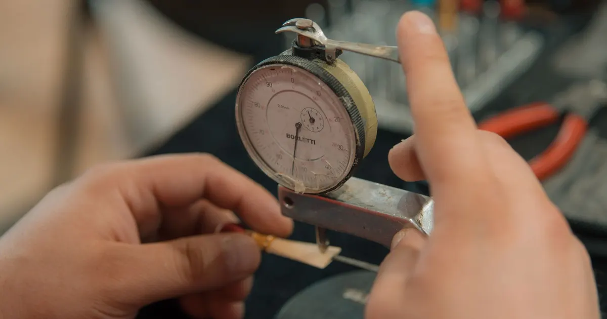
A turned part 1.5 mm wide with a groove 0.2 mm deep is hard to measure with a micrometer. The anvil may be larger than the groove, the jaws may deform the part and a person reading a dial 500 times a day will produce results that vary with the person. This is the situation that vision inspection was developed for.
This guide explains what a vision system measures on small turned parts, where it falls short, what accuracy to expect and when a buyer should ask for it.
The two main kinds of optical inspection
Benchtop vision measuring. A camera looks at a part on a stage, usually under backlight, which makes the outline stand out as a sharp silhouette. Software finds the edges, and the operator or a program measures between them. Good systems also have top lighting to see surface features, and a stage that moves under the camera. They are used for first article inspection, for sampling during a run and for verification of tooling.
In-line or automatic optical inspection. Parts are fed through a station where one or more cameras image each part, and software compares the image to a template or measures key dimensions. Parts that fail are rejected into a separate bin. Glass-disc and rotary systems can inspect many parts per minute and are common on small turned parts that run in the hundreds of thousands. This is how a shop can offer 100% inspection on a feature without a person looking at every part.
An older tool, the optical comparator, projects a magnified silhouette onto a screen with an overlay. It is still useful for quick checks of a profile, but it relies on a person’s eye and leaves no record. A shop that relies on one alone is working to a lower standard of evidence than one with a vision system.
What vision measures well
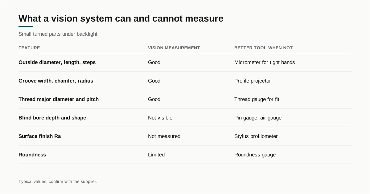
Backlit silhouettes give clean edges, so any dimension that appears in the outline can be measured:
| Feature | Vision measurement | Notes |
|---|---|---|
| Outside diameter | Good | Silhouette width at a chosen position |
| Length and step lengths | Good | Edge to edge along the axis |
| Groove width and position | Good | Silhouette |
| Chamfer length and angle | Good | Profile of the edge |
| Corner radius | Good | Fitted to the outline |
| Thread major diameter and pitch | Good | Silhouette of the thread crest |
| Thread flank angle | Fair to good | Needs enough magnification |
| Tip form and angle | Good | Particularly for points and cones |
| Presence of a feature | Good | Is the groove there, is the cross hole there |
| Burr at an edge | Fair | Visible in profile, not always measurable |
These are the dimensions that matter on needles, pins, shafts and small screws, which is why vision systems are standard in shops that do this work. The inspection guide lists the other methods a shop uses alongside.
What vision does not measure
An optical system sees the outline and the visible face. It does not see inside or below. The list of things it misses is as important as the list it measures.
Internal features. The depth of a blind hole, the diameter inside a bore and the shape of an internal thread are not visible. A through hole can be seen by the light that passes through it, but its diameter at the middle is not available.
Surface finish. A camera shows marks, but it does not give Ra or Rz. A contact stylus or an optical profiler does that.
Roundness and cylindricity. A silhouette gives the diameter at one angle. A part measured at one orientation can be oval and still read the right width. Rotating the part and taking several readings helps, but a dedicated roundness gauge is better.
Form on a non-silhouette surface. A feature on the face of the part, such as a pocket or a flat, appears in top light but has limited height information.
Material and hardness. Vision sees geometry only.
A shop that uses vision for everything is either working with parts whose critical features are all in the outline or is missing something. The drawing’s critical features decide which tools are needed, and the tolerance guide explains how to choose them.
Accuracy to expect
A well calibrated benchtop system, with a telecentric lens and stable lighting, measures a clean silhouette within a few microns. Typical figures, which vary with the system and the part:
| Measurement | Typical uncertainty |
|---|---|
| Diameter of a small round part | about ±0.002 to ±0.005 mm |
| Length | about ±0.003 to ±0.01 mm |
| Angle | about ±0.1 to ±0.5 degrees |
| Radius | about ±0.005 to ±0.01 mm |
These numbers come from the system’s resolution, the calibration and the part’s edge quality. They get worse with burrs, with dirt on the part and with reflections from polished surfaces. Ask the shop for the actual uncertainty on your feature and how often the system is calibrated.
A rule that applies to all measurement is to keep the gauge at least four to ten times more precise than the tolerance it checks. A feature toleranced at ±0.005 mm should be measured by a system good to about ±0.001 mm, which a vision system may not be. For such features, contact or laser methods are the better fit.
Edge quality is the hidden variable
Vision systems measure edges. If the edge is not clean, the measurement is not either. A burr on a turned edge adds length or width, and a polished surface can reflect light into the shadow and shift the edge. A part with a heavy burr on the edge that defines a dimension will read larger than the same part deburred.
This matters for a buyer in two ways. First, the shop has to deburr the part before inspection, or its numbers do not reflect the part you receive. Second, if you inspect incoming parts with your own vision system, you should expect the same effect, and agree on how edges are treated. A drawing note on the edge condition, such as a maximum burr or a break between 0.05 and 0.15 mm, helps both sides measure the same thing.
100% sorting
For high volume and critical parts, automatic optical sorting inspects every piece. The system measures chosen dimensions and checks for visible defects, such as a missing thread, a bent tip or a burr. Rejects go into a bin, and good parts continue.
100% sorting makes sense when:
- A single bad part causes harm, such as a medical or safety part
- The feature is hard to hold in process, so some variation is expected
- The part is cheap and the failure cost is high, for example a part that stops an assembly line
- The customer requires it, and the cost is accepted
It does not make sense when a statistical sample and a stable process give the same protection at a fraction of the cost. Sorting adds cost per part, and it covers only what the camera sees. If the critical feature is a bore, a camera does not check it. The certifications guide explains what quality systems do and do not guarantee, and the supplier audit guide shows how to find out what a shop does in practice.
What to ask a shop
If your part is small and has critical features in the outline, these questions reveal how the shop measures:
- Which critical features do you measure by vision and which by contact?
- What is the uncertainty on this feature, and how is the system calibrated?
- Do you inspect after deburring, and how are edges treated?
- Is there automatic sorting, and what does it check?
- Do you keep the images or measurement records for each lot?
- What happens to parts that fail?
Look for specific answers. A shop that can describe its calibration schedule and show a sample report is one that has used the equipment for real work.
A worked example
Take a stainless pin 0.8 mm in diameter and 12 mm long with a 30 degree tip, a groove 0.15 mm wide and a thread at the other end. The critical features are the diameter, the tip angle, the groove position and the thread.
A micrometer cannot reach the groove, and its anvil would mark the tip. A thread gauge checks the thread fit but not the pitch diameter of a part this small without damage. A vision system handles all four in a few seconds per part. The operator places the pin on the stage, the program finds the silhouette and the report lists the diameter, the tip angle, the groove width and distance from the end and the thread major diameter.
What the system does not check is the surface under the thread, the finish in the groove or whether the thread is torn on the far side. A shop that runs this part will pair vision with a thread gauge and a visual check under magnification. The point is that no single tool covers everything, and a control plan that names each tool for each feature is a sign the shop has thought about it.
How to specify inspection on the drawing
Mark the characteristics that matter and leave the rest. A drawing where every dimension is critical gets every dimension measured, and the cost shows on the quote. A better approach:
- Mark critical dimensions with a symbol and list them in a control plan
- State the sampling plan or the requirement for 100% inspection
- State the measuring method if it matters, particularly for threads and edges
- Agree the first article report format before the first order
- State the record retention if you need to trace lots
Optical inspection is one proof in Swiss machining supplier qualification.
Getting small parts quoted with inspection
Send the drawing and STEP file through the RFQ form. Mark the critical features and state how you expect them to be checked, along with the material and yearly volume. We match the part with up to three shops that run Swiss-type lathes and reply within 24 business hours.
If you require 100% optical sorting or a specific report, say so in the request. A shop that has the equipment will quote it directly, and one that does not will say so before you spend time on a quote that cannot be met.
Frequently asked questions
Can a vision system measure an internal bore?
Only in limited cases. A through hole can be measured by its silhouette when light passes through, and a bore opening can be measured from the face. Depth, taper and the shape inside a blind bore are out of reach for an optical system, and a shop uses pin gauges, air gauges or a contact probe instead.
Is vision inspection more accurate than a micrometer?
Not necessarily. A well calibrated vision system can measure within a few microns on a clean silhouette, which is comparable to a good micrometer. Its advantage is that it measures many features at once, does not touch the part and works on parts too small or too soft for contact gauges.
What is the difference between a vision system and an optical comparator?
An optical comparator projects a magnified shadow of the part onto a screen with an overlay, and an operator compares it by eye. A vision measuring system uses a camera and software to measure the edges and report numbers. The vision system is faster to repeat and produces a record.
Need a quote for this part?
Send the drawing. We match you with up to 3 Swiss shops and reply within 24 business hours.
Get matched with a Swiss shop