Guides / Industries
Nozzle and Injector Parts: Swiss Machining Small Bores and Orifices
October 19, 2026
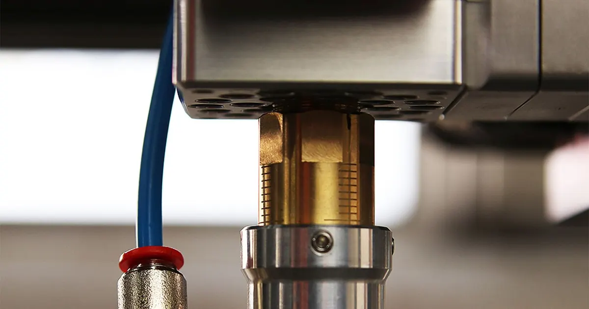
A nozzle is a part whose job is to shape a flow. A small bore, an orifice with a specific edge and a smooth internal path decide how much liquid or gas passes and what pattern it takes. Dispensing tips, spray tips, atomizers, burner nozzles, cleaning jets and the bodies of fuel and fluid injectors all depend on features measured in tenths of a millimeter.
This guide explains how those features are made on Swiss-type lathes, which ones need other processes and how to write a drawing for a part whose performance is a flow, not a dimension.
What a nozzle part looks like
Nozzles share a few features.
An inlet. A larger bore or a cone that collects the fluid.
A transition. A cone, a step or a swirl chamber that shapes the flow on its way to the orifice.
An orifice. The smallest bore, which sets the flow rate. Its diameter and edge define the nozzle’s behavior.
An outlet. The face the fluid leaves, sometimes with a cone or a counterbore to protect the orifice.
An outer body. A shape with threads, a taper, flats for a wrench or a flange for mounting.
Typical materials are brass for general fluids, stainless steel for corrosive or sanitary service, and hardened or coated steels for abrasive flows. Special orifice inserts, such as a ruby or a ceramic disc, are pressed in when wear is a concern.
The Swiss-type lathe makes the body, the inlet, the transition and often the orifice. It is one of the most common machines for this family of parts, because the parts are small, slender and drilled.
How an orifice is made
Three methods compete, and the choice depends on the diameter and the required accuracy.
| Method | Typical smallest size | Accuracy | Notes |
|---|---|---|---|
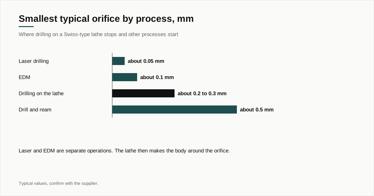
| Drilling on the lathe | about 0.2 to 0.3 mm | about ±0.01 to ±0.02 mm | Fast, in cycle, cone or flat bottom |
| Drilling and reaming | about 0.5 mm | about ±0.005 to ±0.01 mm | Better size and finish |
| Electrical discharge machining | about 0.1 mm or smaller | about ±0.003 to ±0.01 mm | Slow, burr-free, a separate operation |
| Laser drilling | about 0.05 mm or smaller | varies | Fast per hole, cone shaped, a separate operation |
| Press-in jewel or disc | Set by the insert | Very tight | Insert carries the orifice |
For orifices above about 0.3 mm, drilling on the lathe is the economical route and the micro drilling guide covers its limits in detail. For smaller or more precise orifices, EDM or laser takes over and the lathe supplies the body. All figures are typical and should be confirmed with the supplier.
The edge decides the flow
For a given diameter, a nozzle can behave very differently depending on the orifice entry.
A sharp-edged orifice produces a clean jet and a predictable discharge. A rounded or chamfered entry increases flow for the same pressure, since the fluid enters more smoothly. A burr on the exit bends the jet and changes the spray angle. A burr on the entry changes the flow in a way that is hard to predict.
On a drilled orifice, the entry is the surface the drill meets and the exit is where it breaks through. The exit burr is the usual problem, and removing it without rounding the edge is a skill. Methods include:
- Slow breakthrough, to reduce the burr at its source
- Back chamfering from the other side with a small tool
- Abrasive flow or thermal deburring, which remove burrs by flowing abrasive media or burning them off with a gas pulse
- Chemical or electrochemical deburring for hard-to-reach edges
- Brush or ultrasonic methods for loose burrs
Each changes the edge slightly. A flow requirement that is verified after deburring ties the process to the result, and the drawing should say so.
Internal geometry
Inside the nozzle, the shapes matter as much as the orifice.
Drill point cones. A drilled blind bore has a conical bottom, typically about 118 or 120 degrees. The cone is the cheapest shape and often what the flow wants. A flat bottom costs more, since it needs a second tool.
Inlet cones. A cone leading into the orifice improves flow. It can be cut with a form tool or a small countersink.
Swirl ports. Some nozzles have tangential ports that spin the fluid before it leaves, to produce a hollow cone spray. These small cross holes are cut by live tools at an offset from the axis, and the offset and angle are critical.
Counterbores. A stepped bore that protects the orifice or holds an insert.
Finish. A rough internal surface adds turbulence and traps particles. The surface finish guide explains how finish is specified and measured.
The live tooling guide describes how swirl ports and cross holes are cut on the machine.
Materials and coatings
| Material | Typical use | Notes |
|---|---|---|
| Free cutting brass | General fluids, air, low pressure | Easy to machine, see the brass guide |
| 303 and 316 stainless | Corrosive, sanitary, food and medical | See the stainless guide |
| Hardened stainless (416, 420) | Abrasive or high pressure | Heat treated, see the 416 and 420 article |
| Aluminum | Light, low pressure | Soft, can erode |
| Plastics such as PEEK | Chemical and medical | See the PEEK guide |
| Nickel plating or coatings | Wear and corrosion | Thickness affects the orifice |
Coatings reduce the orifice diameter by twice their thickness, so a nozzle with a 0.5 mm orifice and a 5 micron coating on all surfaces ends up at 0.49 mm. The turned dimension has to allow for it.
Service conditions that change the design
The same nozzle shape behaves differently depending on what flows through it, and the drawing is better when it says what that is.
Pressure. A nozzle on a low pressure spray gun can be thin walled brass. One that sees high pressure needs a thicker wall, a stronger material and attention to the thread and seal. The wall around the orifice carries the pressure drop and sometimes needs a hardened insert.
Abrasive fluids. A flow carrying particles wears the orifice, widening it over time and changing the flow. Hardened steel, ceramic or ruby inserts last longer. The turned body then holds the insert and the lathe’s job is the seat, which has to be accurate.
Corrosive fluids. Brass fails in some chemicals. Stainless or a plastic nozzle may be needed, and the choice between them depends on the fluid.
Temperature. Hot gases and liquids expand the part. A press-fit insert can loosen or tighten, and the fit should be set for the operating range.
Cleanliness. Fuel, medical and food applications are sensitive to contamination. A particle left in a nozzle can block it and a film of cutting oil can contaminate a product. Cleaning steps and packaging belong on the drawing.
Clogging. Small orifices clog easily. A sharp-cornered inlet and a smooth bore help particles pass, and a filter upstream is part of the system design, not of the part.
Inspection and flow testing
Dimensional checks are limited for small bores.
Pin gauges. A set of gauge pins in steps of a few microns check the bore diameter. Go and no go pins tell pass or fail.
Optical measurement. A microscope or vision system measures the orifice opening on the face. See the vision inspection article.
Air gauging. Compressed air through the bore measures its size and, indirectly, its finish.
Flow bench. The best test for a nozzle: fluid at a set pressure, a measured flow. Many customers specify the flow, with a tolerance, and treat the diameter as secondary.
Spray pattern test. For atomizers, a photo or a laser pattern checks spray angle and uniformity.
Agree the test method in the quote stage, since a flow rig costs money and calibrations differ. The inspection guide shows how shops and buyers settle these checks.
Cost drivers
| Driver | Effect |
|---|---|
| Orifice size and tolerance | Smaller and tighter means slower cuts, more checks |
| Deburring method | Specialized processes add steps and cost |
| Internal cones and swirl features | More tools, more setup |
| Material | Stainless and hardened grades cost more than brass |
| Flow testing | Per lot or per part, adds time |
| EDM or laser orifice | A second operation outside the lathe |
The cost guide shows how setup and run time combine. For nozzles, deburring and testing often cost as much as machining, so a flow requirement that can be sampled per lot instead of 100 percent tested saves real money.
A worked example
Take a stainless dispensing tip: outside diameter 3 mm, length 18 mm, an inlet bore of 1.5 mm with a conical transition and an orifice of 0.4 mm over the last 2 mm. The tip has a thread for a luer-style fitting at the inlet end.
The shop turns the outside and the thread, drills the inlet bore, cuts the conical transition with a form tool, drills the 0.4 mm orifice from the inlet side and breaks through at the outlet face. A back chamfer and a light abrasive flow step remove the exit burr. The tip is cleaned and checked with pin gauges and a flow test at a set pressure.
The orifice is the risk. At 0.4 mm and a depth of 5 times diameter, drilling is routine in stainless, and the exit burr is the part of the process that varies. A drawing that states the edge condition and the flow target lets the shop choose its deburring method.
What to put on the drawing
- Orifice diameter, tolerance and depth
- Edge condition at entry and exit, with a method of checking
- Flow requirement, with pressure, fluid and tolerance if it applies
- Internal cones and angles, with finish
- Thread or connection standard
- Material, coating and cleaning
- Burr-free requirement and how it is verified
- Yearly volume
Getting nozzle parts quoted
Send the drawing and STEP file through the RFQ form. State the orifice size, the flow requirement, the material and the yearly volume, and mention whether the orifice could be made by another process if the lathe cannot hold it. We match the part with up to three shops that run Swiss-type lathes and reply within 24 business hours.
If your orifice is below 0.3 mm, ask each shop how it makes it. A shop that drills it in cycle, a shop that sends it for EDM and a shop that presses in a jewel are quoting three different parts, and the answer tells you what to expect for price, lead time and consistency.
Frequently asked questions
How small an orifice can a Swiss-type lathe drill?
Orifices of about 0.2 to 0.3 mm are within reach of shops with high speed drilling and good coolant, and 0.5 mm and above is routine. Smaller or more exact orifices, such as those in fuel injectors, are usually made by electrical discharge machining or laser, with the lathe making the body around them.
Why does a small burr matter on a nozzle?
The edge of the orifice shapes the flow. A burr changes the discharge, bends the spray and can break off in service. For liquids and gases the effect on flow can be measurable even when the burr is a few microns tall. Specify the edge condition and how it will be checked.
Is flow tested instead of diameter?
Often both. A pin gauge confirms the diameter and a flow test confirms what the customer cares about, which is how much fluid passes at a set pressure. Because flow depends on edge and finish as well as diameter, many nozzle drawings carry a flow requirement.
Need a quote for this part?
Send the drawing. We match you with up to 3 Swiss shops and reply within 24 business hours.
Get matched with a Swiss shop